TotalView Infrastructure Models
Starting with TotalView 8.11.0, the TotalView debugger supported two infrastructure models that control the way the debugger organizes its TotalView debugger server processes when debugging a parallel job involving multiple compute nodes. Starting with TotalView 8.15, TotalView uses the tree-based infrastructure described below by default.
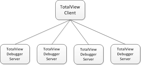
The first model uses a “flat vector” of TotalView debugger server processes. The TotalView debugger has always supported this model, and still does. Under the flat vector model, the debugger server processes have a direct (usually socket) connection to the TotalView front-end client. This model works well at low process scales, but begins to degrade as the target application scales beyond a few thousand nodes or processes. This is the default infrastructure model.
Figure 257 shows the TotalView client connected to four TotalView debugger servers (
tvdsvr). In this example, four separate socket channels directly connect the client to the debugger servers.
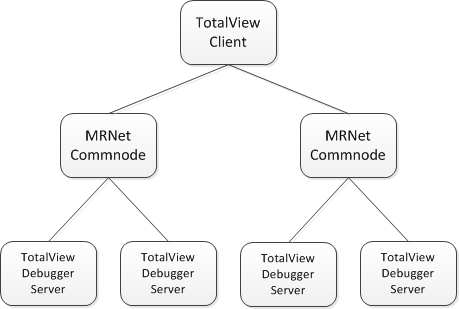
The second model uses MRNet to form a tree of debugger server and MRNet communication processes connected to the TotalView front-end client, which forms the root of the tree. MRNet supports building many different shapes of trees, but note that the shape of the tree (for example, depth and fan-out) can greatly affect the performance of the debugger. The following sections describe how to control the shape of the MRNet tree in TotalView.
Figure 258 shows an MRNet tree in which the TotalView client is connected to four TotalView debugger servers through two MRNet commnode processes using a tree fan-out value of 2.


